- Infrastructure
- Conventional lines
- Heavy haul
- High speed
- Field of application
- Track
- Switch
- Working mode
- Continuous action
Highlights
- Continuous action production and switch track-tamping machine with high production rates
- Split head tamping unit design for turnout tamping with three-point auxiliary turnout lifting system achieving high working quality and lowering long-term maintenance costs
- Integrated stabilizers reduce the necessary number of operators of the surfacing gang and reduce the time of the required slow order after surfacing.
- PLC touch screen controls for easy diagnoses and trouble shooting
- Automatic Geometry Guidance System (AGGS) and Automated Tie Locating and Analyzing System (ATLAS)
- Continuously moving machine frame reduced the impact on the operator during the indexing process of the tamper
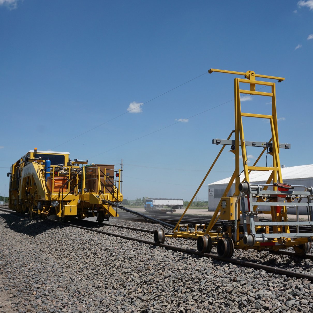
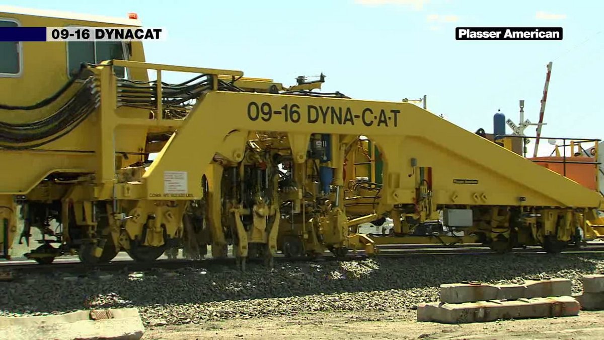
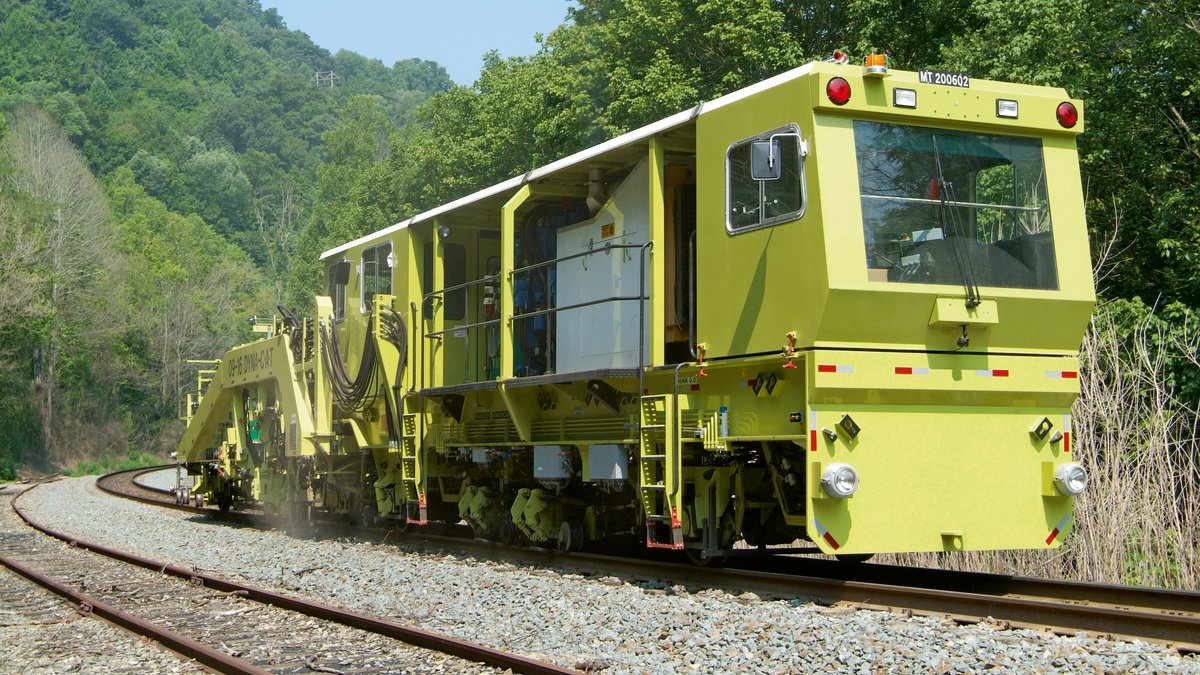
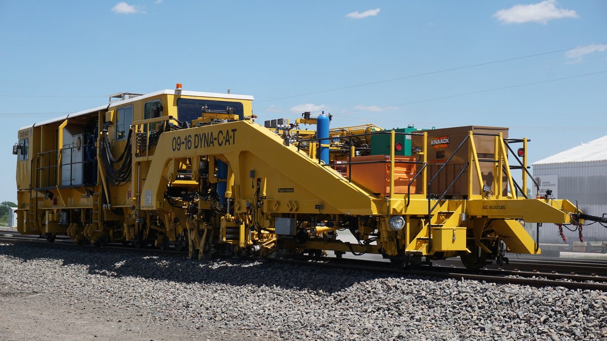
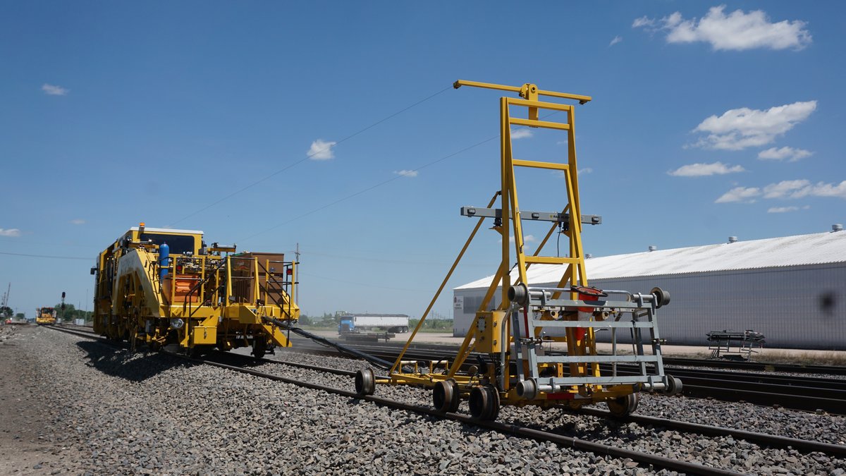
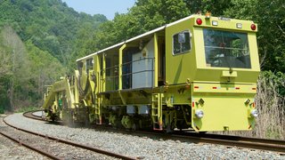
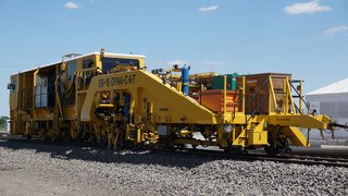
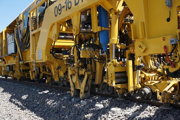
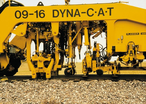
The Plasser 09-16 DYNACAT is a heavy-duty, high speed, continuous action switch and production track tamping machine with an integrated dynamic track stabilizer. Tamping and lifting units are mounted on a separate satellite frame that is attached to the main frame. While the satellite indexes from tie to tie during the actual work process (lifting, lining, cross-leveling, and tamping), the machine’s main frame with stabilizer system moves smoothly and continuously. The operator’s cabin, power unit, main hydraulic components, electronic systems, etc., are installed on the main frame.
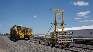
The machine is standard equipped with a PLC CAN bus control system and fully automatic, computer-controlled (AGGS) lifting, leveling and lining systems. Dynamic track stabilization provides controlled, accurate track settling with the aid of a reference system.
Optionally, the 09-16 DYNACAT can be equipped with Plasser’s Automated Tie Locating Analyzing System (ATLAS).
Plasser Continuous Action Tampers have been working successfully on major world railway systems since 1983, providing optimum “return on investment” of track maintenance expenditures.
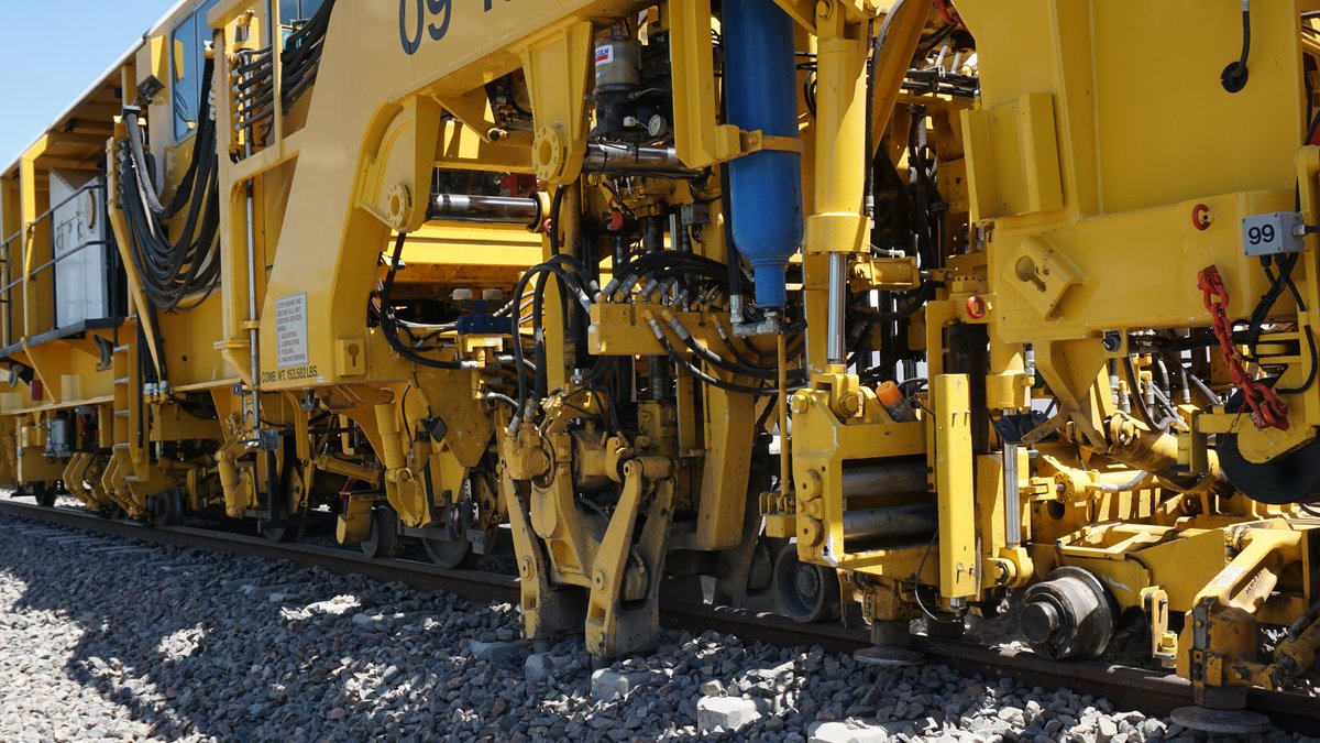
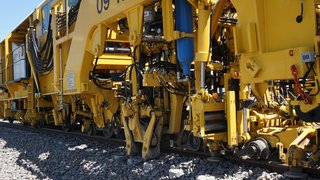
The Tamping Unit consists of four, 4-tool, non-synchronous tamping heads, housed in two separate frames with ballast consolidation performed via a vibratory hydraulic squeeze system. Each frame is laterally adjustable to allow complete switch tamping and splits into two, 4-tool sections. Each of the 4-tool, tamping unit heads can be individually controlled. This unique, “split head” system provides several major advantages over other switch tampers. Each unit is raised and lowered vertically instead of at an angle. This provides more uniform ballast compaction. Each 4-tool head concentrates ballast compaction near the rail base area where it is needed most. Unnecessary tamping at or beyond tie ends or center binding is eliminated. Individual control allows complete switch tamping with a minimum of horizontal tamping unit adjustment, thus reducing the amount of time required to tamp a switch. Tamping unit depth control is easily adjusted from the work cab to allow proper ballast compaction under varying track conditions. When using the machine as a production tamper, all four units are raised and lowered in unison, providing the same thorough tamping action for which all Plasser tampers are known. An automatic tamping unit lubrication system is installed with all Plasser Tampers.
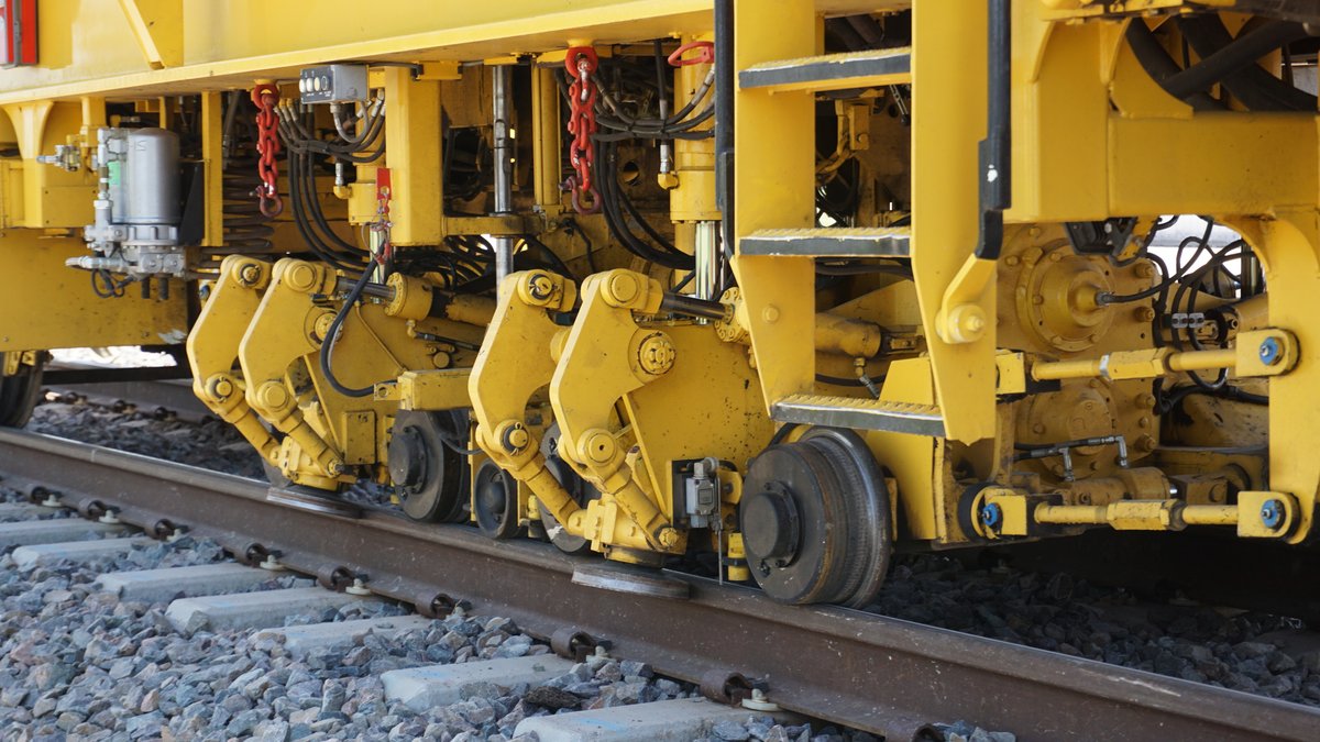
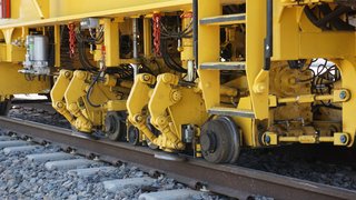
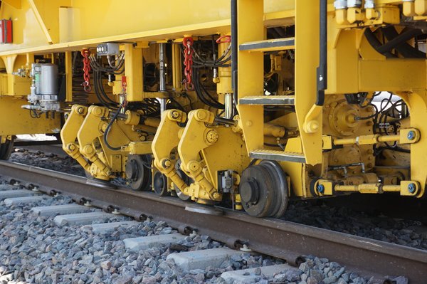
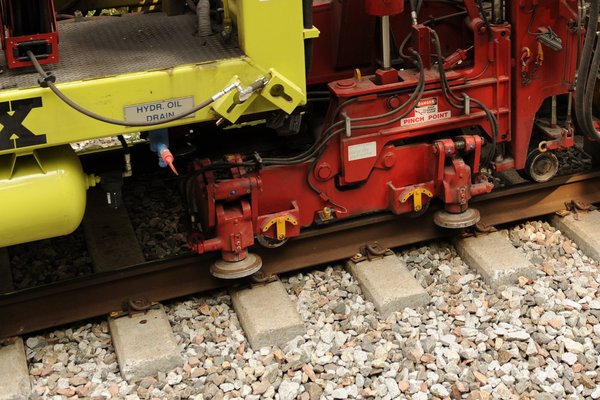
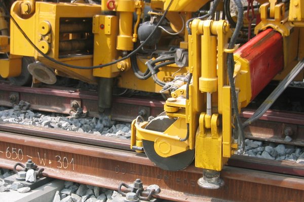
The machine is equipped with two, heavy-duty, hydraulically driven, vibratory stabilizing units. These units roll on eight, heavy-duty, flanged wheels (4 per unit) and clamp to the rail head via hydraulically operated roller discs (2 per unit). The roller design allows. to stabilize switches, unlike designs utilizing double-flanged rollers. Stabilization is performed continuously. For travel, the units are raised and locked up hydraulically. Vibration amplitude and down force are automatically controlled by the machine's electronic measuring and control system. The essential parameters for the effectiveness of the Dynamic Track Stabilizer are stabilizing frequency, vibrating amplitude, work speed, size of the stabilized area, and vertical down force.
Based on measurements and tests conducted by various railroads, railroad research centers, and Plasser’s experimental and research department, the relationship between the individual operating parameters and their effect on the stabilization of the track is known (controlled settlement and lateral resistance). Increasing the stabilizing frequency, vibrating amplitude and vertical down force improves the machine’s effectiveness, reducing the work speed achieves a positive result. The size of the work area is determined by the number of stabilizing units. By utilizing two units on the DYNACAT., the latest technological theories are now reality.
A heavy-duty, combination track lifting and lining clamp provides for complete switch and plain track production work. The DYNACAT is equipped with two large lifting and two large lining cylinders. Each rail is lined by two flanged rollers. Lifting is carried out by roller lifting clamps gripping the rail head whereby the rollers can remain closed during forward motion, depending upon the track design, or can be opened and closed automatically. In switches and crossing, the lifting hook is applied. The rail hook is guided to the rails from the outside and grips either the rail head or the rail base. The clamp is completely adjustable laterally and longitudinally, as well as rail hook depth, from the operator's cab, and allows lifting and lining at every point in a switch. In heavy ballast conditions, the hook and roller clamp may be used at the same time. A remote control is also provided for positioning the clamp assembly when tamping a switch by an additional operator, or supervisor on the ground.
The Plasser Integrated Auxiliary Turn-out Lifting System consists of a hydraulically-operated, telescopic, auxiliary-track-lifting clamp mounted on each side of the machine adjacent to the main track-lifting clamp. These clamp assemblies provide a precisely controlled lift of the outside turn-out rail during switch-tamping operations. The auxiliary clamps are controlled from the operator's cabin, with the amount of lift determined automatically by the machine's electronic surfacing and cross-level control system. The use of the system during switch tamping operations greatly reduces stress applied to rail fasteners, ties and rails, and applies uniform lift at three points in the long tie areas of switches. The need for cumbersome, manually placed track jacks, hydraulic hose reels, and the related maintenance cost is eliminated. Labor costs can be reduced; and safety hazards associated with the placement and operation of conventional track jacks during switch-tamping operations are eliminated. Due to the system's integrated design and its lifting function that coincides with main machine operations, overall performance is greatly enhanced.
Technical data 09-16 DYNACAT
| Production rate | up to 3 200 | feet/hour |
| Length | 89' | |
| Width | 10' 6'' | |
| Height | 12' | |
| Weight | 153 500 | lb |
| Wheel Diameter | 28'' | |
| Engine Power | 525 | HP |
| Travel Speed | 45 | mph |
